
How to Size a Fan for a Ducted Fume Cupboard: A Practical Guide

James Cox
Project Manager
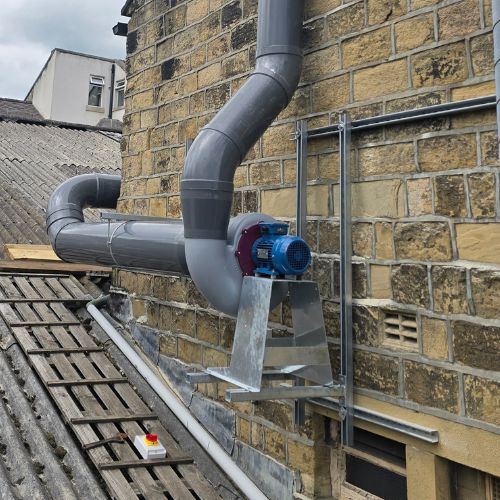
When specifying or upgrading a fume cupboard, selecting the right fan is crucial for both safety and performance. Whether you're designing for a school, university, pharmaceutical lab, or industrial site, the fan must achieve adequate airflow and overcome system resistance, all while complying with BS EN 14175.
1. Understand Fume Cupboard Airflow
As per BS EN 14175-2:2003 Clause 8.1, the standard face velocity for a ducted fume cupboard is 0.3 to 0.5 m/s. Most UK specifications aim for 0.5 m/s across the sash opening. It's important to note that the fume cupboard being used must be type tested at the face velocity to ensure it will sufficiently contain the fumes.
The total volume flow rate is calculated from:
Q = A × V
Where:
- Q = Airflow in m³/s
- A = Sash opening area in m²
- V = Face velocity (e.g., 0.5 m/s)
2. Calculate Volume: Worked Example
Let's size a fan for a 1500 mm wide bench-mounted fume cupboard (like the K8 series) with:
- Sash opening height = 500 mm (0.5 m)
- Opening width = 1200 mm (1.2 m)
A = 1.2 m × 0.5 m = 0.6 m²
Q = 0.6 m² × 0.5 m/s = 0.3 m³/s (or 1080 m³/h)
3. Calculate System Pressure Drop
Your fan must overcome resistance (static pressure loss) from:
- Fume cupboard (e.g., 60 Pa)
- Duct runs (straight ductwork adds ~2 Pa per metre)
- Bends/elbows (each adds ~20-30 Pa)
- Terminal devices or stack cowl (10–20 Pa)
- HEPA/carbon filters if fitted (can be 100+ Pa)
To calculate pressure drop in a straight pipe at a certain velocity, you can use our free calculator!
Worked Example:
- 10 m of straight duct: 20 Pa
- 3 x 90° bends: 3 × 20 = 60 Pa
- Cupboard baffle: 60 Pa
- Terminal/stack cowl: 15 Pa
Total Pressure Drop ≈ 155 Pa (20 + 60 + 60 + 15 Pa)
This is your external static pressure (ESP) requirement.
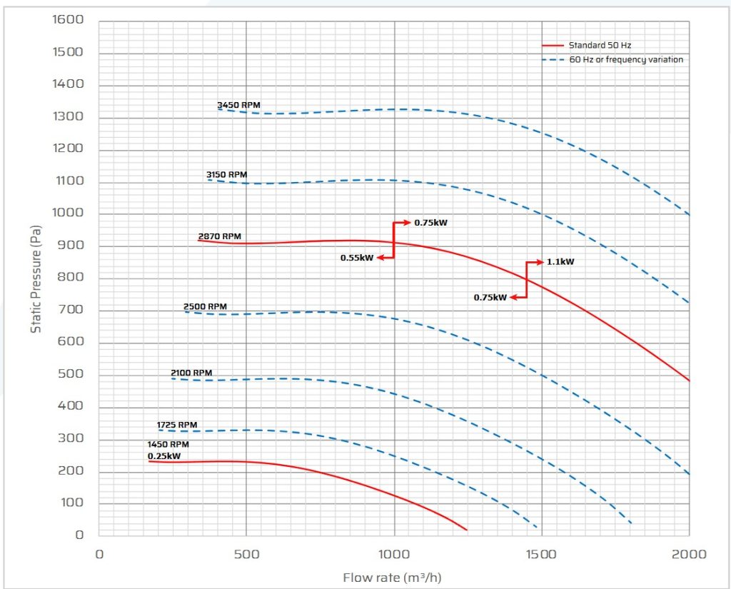
4. Reading a Fan Curve
A fan curve plots airflow (x-axis) vs static pressure (y-axis).
- Locate your duty point: in our case, 1080 m³/hr @ 155 Pa
- Ensure it lies on the fan's performance curve (not beyond it)
- For typical fume cupboard installations, 1400rpm fans have a good balance of pressure and volume. 2800rpm fans are more suitable for LEV arms and high pressure systems (which may feature filters or scrubbers)
- Each fan has a performance curve specific to its build and design.
5. Validate with BS EN 14175
After installation, test your system in line with:
- BS EN 14175-4:2004: On-site test methods
- Face velocity test
- Extract volume flow rate
- BS EN 14175-3: Type testing
- BS EN 14175-6: for Variable Air Volume (VAV) systems
6. Fan Sizing Example: Summary
| Parameter | Value |
|---|---|
| Sash Opening | 1.2 m × 0.5 m = 0.6 m² |
| Face Velocity | 0.5 m/s |
| Air Volume Required | 0.3 m³/s (1080 m³/h) |
| Pressure Drop Estimate | 155 Pa |
| Recommended Fan | Centrifugal fan rated for 0.3 m³/s @ 155 Pa (or higher) |
7. Final Tips for Specifiers
- Include 10–20% safety margin on fan capacity
- Use variable speed drives (VSDs) or VAV dampers for energy efficiency
- Match fan materials to chemical compatibility (typically polypropylene)
- Use airflow alarms per BS EN 14175-2, Clause 8.2
Conclusion
Correct fan sizing isn't just about airflow: it's about ensuring safe containment, energy efficiency, and full compliance with BS EN 14175. With proper calculations and validation testing, you'll deliver a fume cupboard system that performs reliably for years.